ARMfuck: Turing completeness from two RISC instructions
Why did I do this?
- Intro/Context
- Register Map
- Some building blocks
- Numbers
- Writing the Interpreter
- Bootstrapping for the GBA
- Additional Links
Intro/Context
Thanks to making the program counter a general purpose register (henceforth referred to as pc or r15) and showing its actual (i.e. pipelined) value instead of the address of the current instruction, the ARM architecture has many rather “fun” edge cases. The LDM and STM instructions in particular are so bad that they’ve become a meme on the emudev Discord server. A couple of us have realized and joked about how they’re even turing complete, but that never went beyond a funny thought experiment until now.
First, some extra constraints I set myself that are important to keep in mind.
- This project is meant to run on a Game Boy Advance. That means I’ll be working with the ARM7TDMI, which uses the ARMv4T instruction set, although THUMB won’t be used at all. There isn’t a technical reason for this; I’m just very familiar with it and its particular edge cases.
- The core functioning of the code shouldn’t rely on anything GBA-specific. I’m trying to show that ARM is turing complete, not the GBA. That means no DMA, no abusing weird behavior from reading/writing 32-bit values to certain memory regions, no open bus, etc. Some things will impossible to make platform independent like input, output, and memory maps.
- No BIOS functions. This is less of a rule and more of a clarification. Triggering an interrupt or running a software interrupt (by way of jumping straight to the handler since
SWIisn’t allowed) would run instructions in the BIOS that, much to my dismay, aren’tLDMorSTM. Truly Nintendo’s biggest missed opportunity.
This project owes its existence to Zayd’s LDM/STM only version of gang.gba. Even though it’s much simpler, I never would have thought something like this was possible without it. I’ll try to mention when I use techniques from it in this project.
What are LDM and STM?
If you’ve never written ARM assembly, you’re probably a little confused because you don’t know what LDM and STM are. And if you have written ARM assembly, you’ve been perpetually confused ever since you learned about them. LDM and STM were instructions in 32-bit ARM that allow you to load or store any combination of the 16 GPRs consecutively in memory using a single instruction. The different options in addressing mode allow them to implement full descending, empty descending, full ascending, and empty ascending stacks while simultaneously returning from a subroutine. To give a common example, push {r0, r2, r14} and pop {r0, r2, r15} get encoded as stmdb r13!, {r0, r2, r14} and ldmia r13!, {r0, r2, r15} respectively.
Here’s their encoding. I’ll try to summarize what everything is and how it’s useful, but you should really read the manual and GBATEK for the full information.
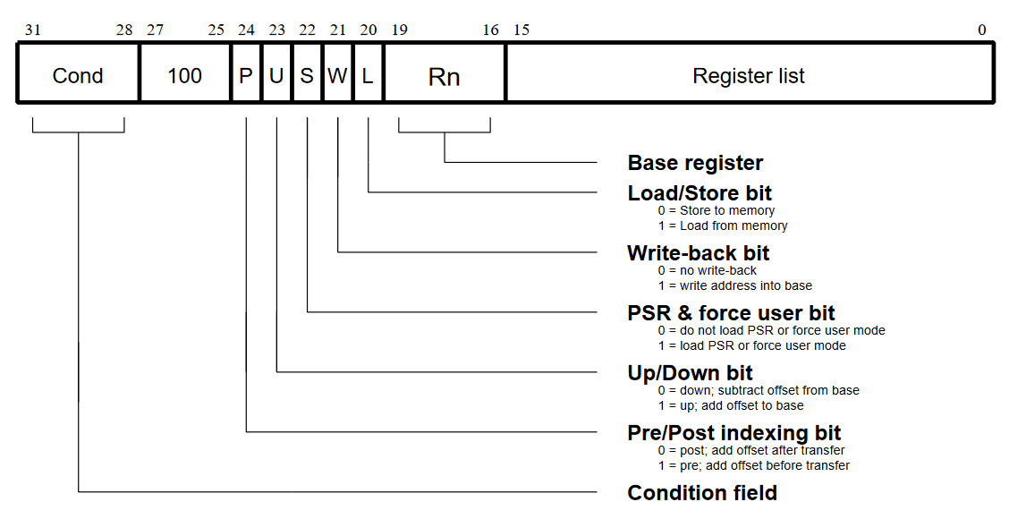
Register List: Each bit can select one of the GPRs. Regardless of the addressing mode, they’re stored in ascending order in memory. Loading into r15 is an alternative way to do a branch. There’s also an edge case where an empty register list will load/store r15 and increment/decrement the base register by 0x40, but I haven’t found a situation where it’s useful.
Base Register: The value in this register is used as the base address.
Load/Store bit: Determines whether the instruction is an LDM (load registers) or STM (store registers). All the other bits behave the same for both instructions.
Write-back bit: Denoted by a ! after the base register. Probably one of the most important features of this instruction and also why many. It writes the address of/after the last-transferred* register back to the base register. It gets “fun” because when you have writeback enabled and include the base register in the register list, the exact behavior depends on how the instruction works at a cycle level, the number of registers your loading/storing, and the position of the base register in that list. There’s code in the BIOS and NDS firmware that relies on this behavior too.
PSR & force user bit: There’s some really fun edge cases here. Luckily for any everyone, I have no control over what mode I’m in, so it’s irrelevant.
Up/Down bit: Denoted by an i/d for up/down respectively. Determines whether the registers to be loaded/stored should be above or below the base address.
Pre/Post indexing bit: Denoted by a b/a for pre/post respectively. On top of the space needed to store the registers, another increment/decrement is performed to the base address. This determines whether it happens before the loads/stores or after them. Either way, it gets applied to the writeback address. If I did a bad job explaining that, please look at the manual. It has nice graphics that explain this much better than I can.
Condition field: All instructions on ARM are conditional. Since I can’t set any of the flags, this is nearly useless. Even if I could (archimedes port wen), I might disallow it for violating the spirit of the challenge. I can use it to make executing data as code easier, but that’s hard, and I’m lazy.
Notes on the pipeline
ARM has a 3-stage pipeline that’s visible to the user. That means two things to us.
- The two instructions immediately following the current one are stored in the pipeline. If you modify them, the old instructions will be executed unless you branch or try to run them again.
r15is the address of the current instruction (which I’ll be calling$from now on) + 8 on the first cycle of an instruction and$ + 12on any other cycles. To spare you the details of how the instructions work on the cycle level, we get$ + 8when usingr15as the base register and$ + 12version when storing it.
Where do we even start?
The method suggested by me and Atem was to make a modified version Bytepusher/ByteByteJump, a single-instruction computer that works purely by copying bytes around and unconditionally jumping. On the surface this seems like the obvious choice: all we have is memory load/store instructions and all we need to do is load/store memory. There’s a couple problems here:
LDM/STMcan only move a whole word at a time, while ByteByteJump moves single bytes. This makes it impossible to modify parts of addresses, which makes LUTs and most other Bytepusher programming strategies impossible.- The GBA has a fraction of the Bytepusher’s 16MB of RAM and what it does have is located in different parts of the memory map.
- Even if I found a hack to get over the first hurdle, none of the existing programs would work and I anything I run on this would have to be custom written.
My next thought was Brainfuck. Brainfuck is an esoteric programming language with 8 simple commands that can move a pointer back and forth, increment or decrement a memory cell, input or output a single ASCII character, and loop until a memory cell is 0. The first 4 are trivial, output’s easy, input isn’t hard to kludge in if you stretch the definition a bit, and the only real challenge is detecting if a number is 0 for the loop instructions. It’s very popular, has virtually zero system requirements (if you ignore the infinite memory part), there’s many programs written for it, and, most importantly, most of those programs will run on any cursed implementation you want without any modifications.
Register Map
Not sure where else to put it. These are aliases I assigned to the registers for readability. They’ll be used throughout the code examples.
| Register | Alias | Description |
|---|---|---|
| r0 | dat | General purpose data |
| r1 | ptr | General purpose pointer |
| r2 | tmp | Trash. Mostly used by macros and increments/decrements |
| r3 | tmp2 | |
| r4 | tmp3 | |
| r5 | tmp4 | |
| r6 | tmp5 | |
| r7 | tmp6 | |
| r8 | tmp7 | |
| r9 | tmp8 | |
| r10 | vram | Pointer to where the next character will be in the framebuffer |
| r11 | cp | Pointer to the next instruction |
| r12 | dp/lp | Pointer to the current data cell/position in the literal pool |
| r13 | sp | Stack pointer. This is the one thing in the entire program that’s normal |
| r14 | input | Pointer to the current location in the input buffer |
Some building blocks
Before we go writing code with these instructions from hell, it might help to replicate some common functions.
Note to people reading the code: Whether the macros are used is sort of random. Sometimes they can be modified to save instructions in a particular situation, sometimes I decided to make a chuck of code into macro after writing it, sometimes they ended up not being useful for this project, and sometimes I simply forgot to use them.
nopl - The classic (pseudo)instruction that just does nothing. Basically anything using just the tmp registers works for this. I called it nopl because the assembler already has an alias for nop. This is surprisingly useful for self-modifying code and navigating around the pipeline.
ldmia tmp, {tmp}inc - Increments a register by 4. A simple example of how writeback can be used to extend the functionality of these instructions. More tmp registers can be added to add more.
ldmia reg!, {tmp}dec - Same as INC but with a decrementing LDM
ldmia reg!, {tmp}mov - Copy a value from one register to another. Simply push a register onto the stack and pop it into another one. Not used here, but I saw it in Zayd’s ROM and thought it was worth mentioning.
stmdb r13!, {src}
ldmia r13!
call - Calls a subroutine. A NOP has to be added either before or after the LDM because the STM pushes $ + 12. It could theoretically be used like a MIPS branch delay slot.
stmdb sp!, {r15} ; Push return address onto the stack
nopl
ldmia reg, {r15} ; Jump to the handler
ret - Returns from a subroutine. Really nothing special here. It’s standard LDM use.
ldmia sp!, {r15}load - Unless I have a register pointing somewhere else, I can only reliably load data from the three words immediately after the current instruction. I can work around that by loading the value into the register and then skipping over it by loading a different value into r15.
ldmia r15, {reg\}
ldmia r15, {r15\}
dw val
dw $ + 4
Thank you to Zayd for pointing out both loads can be combined into a single instruction (this is ldM after all, not ldR). Unfortunately fasmarm doesn’t like this and I can’t use the dw workaround because it’s in a macro. I might go back and replace all the uses of the macro with the smaller version one day.
ldmda r15, {reg, r15}
dw val
dw $ + 4
execptr - Self modifying code, our key to conditional execution. This macro executes the instruction pointed at by ptr. Remember that the two instructions after the current one are stored in the pipeline, so we need to overwrite the third one and make the other two instructions in the pipeline nops. Again, they could probably be used like a MIPS load delay slot.
ldmia ptr, {tmp}
stmib r15, {tmp}
nopl ; Empty pipeline
nopl

nopl ; To be replaced
condjump - a.k.a. the if statement - I can’t think of a good way to introduce this. There are two possible jump addresses. You can use one instruction to jump to the first address or another instruction to jump to the second address. If you pretend those instructions are true/false and load them from a variable using execptr, you can approximate an if statement.
;if *ptr then
;  goto op1
;else
;  goto op2
;
;Where:
; true/Option 1 = ldmdb r15, {r15}
; false/Option 2 = ldmia r15, {r15}
execptr

dw op1 ; Option 1
dw op2 ; Option 2
select - a.k.a. the ternary operator - If you only want to load different values into a register based on a condition, having a separate jump location for each value might be overkill. You can take a note from how we load values to simplify the previous macro into something like
; dat = *ptr ? op1 : op2
;
;Where:
; true/Option 1 = ldmia r15, {dat}
; false/Option 2 = ldmib r15, {dat}

execptr
ldmib r15, {r15\} ; Skip to end
dw op1 ; Option 1
dw op2 ; Option 2
dw $ + 4
Numbers
So how do I tell if a number is 0? There isn’t a way to modify part of the instruction with our value Bytepusher-style, I can’t use it as a LUT index because the bottom two bits will always get masked off one way or another, and it’s not a safe assumption you’ll be able to put custom data at the bottom of the address space since that’s where ARM puts its vector table anyway (it’s only possible on the GBA through the use of an undocumented register that doesn’t exist on the DS or most emulators). The short answer is I don’t.
If there’s one thing I’ve learned from set theory and lambda calculus, it’s that I’m way too stupid to ever learn set theory and lambda calculus. My only real takeaway was that numbers don’t have to be numbers; they can be any weird representation you want as long as it ends up working consistently. In my case I used a doubly linked list. Instead of “numbers” each data cell holds a pointer into a “number table” that’s created at compile time (assemble time?) and stores data associated with each number. Each entry has pointers to its adjacent entries, a pointer to the graphical data for its associated ASCII character, and a “boolean” that’s true if the number is 0 (recall the hacky version of if from last section).
Another small hack I did was offsetting the pointers by 4. LDM can access the words directly before and after the base address, with no penalty so doing this gives instant access to isZero and easier access to glyph while keeping next and prev accesses the same.
// You can imagine each number as something like this
// The offset pointer can't be shown in C syntax
struct Number {
    Number *next;
    Number *prev;
    bool isZero;
    Glyph *glyph;
};
Incrementing and decrementing a number stored in a register can be done in one instruction:
ldmdb reg, {reg} ; num_inc

ldmia reg, {reg} ; num_dec
Linked lists would normally be a horrible choice for something like this because of their O(N) access times, but that isn’t an issue here. Brainfuck can only ever increment or decrement a value by one, so random access times don’t matter. If I really wanted to, I could compare arbitrary numbers and perform more complex operations by incrementing/decrementing in a loop like a pseudo-brainfuck.
One more problem I ran into is how to deal with large numbers when I have limited memory. Thankfully many Brainfuck implementations limit data cells to 8 bits with standard overflow/underflow behavior. All I have to do to implement this is make the next field of 0 point to 255 and the prev field of 255 point to 0.
Writing the Interpreter
Dispatch
Before I can implement the commands, I need a way of determining which one to execute. For the same reason we can’t use numbers directly, we need to change our definitions find another way of representing them. That means we’ll also need a script to convert from normal Brainfuck to our custom representation. And since no one has to write this custom representation, we might as well make it as easy on ourselves as possible. Each “command” is really just the address of its handler, so dispatch is little more than (*cp)(); or call cp.
So I don’t have to hardcode the handler addresses and change them every time I modify the code, I put a list of important addresses at the end of the file. That way the loader script can read them and adjust automatically every time you load a program.
Moving the Data Pointer
Let’s start with the > and < commands, which move the data pointer left and right. The data pointer is stored in a register, so these can be done in one simple instruction.
command_right:
    ; ++dp
    inc dp
    ret

command_left:
    ; --dp
    dec dp
    ret
Modifying Data
Next is + and -. I’ve already been over how the “numbers” are implemented and how to increment/decrement them.
command_inc:
    ; *dp += 1
    ldmia dp, {dat}
    num_inc dat
    stmia dp, {dat}
    ret

command_dec:
    ; *dp -= 1
    ldmia dp, {dat}
    num_dec dat
    stmia dp, {dat}
    ret
Output
The GBA gives me three options for graphical output:
- Framebuffer mode. Not a lot to say here. I can control individual pixels by writing a 16-bit color value or an 8-bit palette index to VRAM.
- Tiled backgrounds. Write the character’s tile index and you’re done, right? Once again, the 32-bit write limitation comes back to bite me. Each tile is represented by two bytes, so I can’t set one tile without destroying another. All writes to VRAM get forcefully aligned too, so I can’t do any trickery there.
- Objects (a.k.a. sprites). These are like squares/rectangles of tiles that can be freely moved around the screen by changing the coordinates. Each object is represented by an 8-byte entry in OAM and I can change the tile index without overwriting anything I care about. The problem with this method is the GBA’s PPU only has space for 128 objects. For a screen that can display 600 characters, this isn’t enough.
For my first revision of the . command, I went with option 1 and the 8-bit palette indexes because it seemed like the obvious choice. The framebuffer mode is indexed like a 2D array where the address of any pixel can be computed by (y * 240) + x. To draw an 8x8 character, I ha to copy 8 bytes from the tile data to VRAM, add 240, and repeat 7 more times. This got pretty cumbersome and I wasn’t proud of the code, especially since I needed a workaround to keep the VRAM pointer in the right place and it glitched out when I hit the end of a line.
My second revision was a hybrid of options 1 and 2. I know writing the tile index isn’t feasible, but what if I wrote the tile data instead? Within an 8x8 tile, the first 4 (or 8 bytes if you use 256 color mode) bytes are the first row, the next 4 are the second row, and so on. With this layout, I can write an entire tile in only one instruction and start writing the next without any extra math or adjustment. If I hardcode the tile indexes to be incrementing values and skip non-visible tiles, I’ve effectively made a framebuffer that handles line wrapping for me.
TL;DR: I turned tile mode into framebuffer mode with a better memory layout.
command_out:
    ; putchar(*dp)
    ldmia dp, {dat} ; ptr = *(*dp + 8)
    inc dat
    ldmib dat, {ptr}

    ; Copy tile data from ROM to VRAM
    ldmia ptr, {tmp-tmp8}
    stmia vram!, {tmp-tmp8}
    ret
Input
I’m not writing a keyboard interface with only LDM and STM. I probably could, but I really don’t feel like it. Instead, I took a note from lazy esolang designers and made input a string that’s hardcoded into the program. The program loader script converts each character of the input text into the number table entry for its ASCII code and inserts it at a known point in the ROM. This is more for the sake of completeness than being usable.
command_in:
    ; *dp = getchar()
    ldmia input!, {dat}
    stmia dp, {dat}
    ret
Loops
Time for my two favorite commands: [ and ]. [ checks if the current data cell is 0 and jumps to the matching ] if it is. Otherwise, it continues executing instructions as normal. ] is the opposite. It jumps to the matching ] if the current data cell is not 0 and continues executing instructions if it is.
The first part’s easy. We load ptr with the address of the current cell’s isZero field and use the condjump macro from earlier.
; I will be showing the unoptimized version here because it's easier to understand
command_open:
    ; if (!dp->isZero) return;
    ldmia dp, {ptr}
    inc ptr ; Point at isZero
    condjump open_cont, loop_end
open_cont:
    ...

command_close:
    ; if (dp->isZero) return;
    ldmia dp, {ptr}
    inc ptr ; Point at isZero
    condjump loop_end, close_cont
close_cont:
    ...

loop_end:
    ret
Now we have to find the matching symbol. dat will hold a number (the linked list kind) that keeps track of how deep we are. As we scan backward/forward through the instructions, encountering a [ will add 1, encountering a ] will subtract 1, and everything else will do nothing. When it reaches 0, we’ve hit the matching bracket and can quit the loop. We’ll obtain the offsets by prefixing each handler with inc_num dat, dec_num dat, or nopl and executing said instruction in our loop.
Prefixes:
	nopl
command_right:
    ...

    nopl
command_left:
    ...

    nopl
command_inc:
    ...

    nopl
command_dec:
    ...

    nopl
command_out:
    ...

    nopl
command_in:
    ...

    num_inc dat
command_open:
    ...

    num_dec dat
command_close:
    ...
Final code:
    num_inc dat
command_open:
    ; if (!dp->isZero) return;
    ldmia dp, {ptr}
    inc ptr ; Point at isZero
    condjump open_cont, loop_end
open_cont:
	load dat, number_table + NUMBER_SIZE + 4 ; dat = 1
open_loop:
    ; Apply the instruction's stack level offset
    ldmia cp!, {ptr}
    ;dec ptr
    ;execptr
    ldmdb ptr!, {tmp}
    stmib r15, {tmp}
    nopl
    nopl
    nopl ; Will be replaced

    ; if dat == 0: break;
	mov ptr, dat
	inc ptr ; Point at isZero
	condjump loop_end, open_loop
num_dec dat
command_close:
; if (dp->isZero) return;
ldmia dp, {ptr}
inc ptr ; Point at isZero
condjump loop_end, close_cont
close_cont:
load dat, number_table + (NUMBER_SIZE * 255) + 4 ; dat = -1
dec cp
close_loop:
; Apply the instruction's stack level offset
ldmdb cp!, {ptr}
;dec ptr
;execptr
ldmdb ptr!, {tmp}
stmib r15, {tmp}
nopl
nopl
nopl ; Will be replaced
; if dat == 0: break;
mov ptr, dat
inc ptr ; Point at isZero
condjump loop_end, close_looploop_end:
retA Secret 9th Command
How do we know when the program is done and we can stop executing instructions? Well, how does your computer know when it reaches the end of a string? It would go on forever printing random garbage if it didn’t have a null terminator. In the same way, the interpreter will continue and try to execute random data for the rest of eternity, so let’s give it a null terminator. It takes the form of a special “halt” command appended to the end of the program by the loop. This command tries putting the system into a low-power “stop” mode and then loops infinitely if it fails.
command_halt:
    ; Try to put the system into stop mode
    dw 0xE89F8003 ; ldmia r15, {dat, ptr, r15}
    dw 0
    dw 0x8000
    dw REG_HALTCNT - 1
    dw $ + 4

    ; Loop infinitely
    ldmdb r15, {r15}
    dw $ - 4
Bootstrapping for the GBA
Before the interpreter can run, some things need to be initialized. The bootstrap is located in ROM and does 7 things:
-
Jump to the entrypoint of the program
After the BIOS runs, it passes off control of the game by jumping to address 0x08000000, the start of the cartridge’s address space. The first 192 bytes of the cartridge are taken up by a header that contains information about the game, a checksum complement (handled by
headercompliment.py), and some logo data (this was Nintendo’s attempt using the trademark system as an anti-piracy measure, but it doesn’t actually hold up in court lmao). The first 4 bytes are space for aBinstruction that branches to the start of the program. We haven’t run any instructions and there’s already a problem. Thankfully, Zayd already solved this problem in hisgang.gbaROM. 12 bytes after our first instruction, the logo has the value0x0A82843D, which conveniently is an address somewhere in the middle of cartridge mirrors. After that, he puts a short bit of code at0x0882843C(adjusted for alignment and mirroring) to jump to the start of the program.
        _start:
        .word 0xE9BF8000 @ ldm pc!, {pc} (unconditional branch to 0x0A82843D, a convenient value obtained
                        @ from the nintendo logo)
    . . .

    .org 0x0082843C
    nintendo_logo:
        .word 0xE9BF8000 @ ldm pc!, {pc} (unconditional branch to main)
        .word 0x0
        .word 0x0
        .word main
I translated it to fasmarm, reduced the branch to main by 8 bytes with a `ldmdb`, and removed the writebacks to `pc` because it was useless and makes the assembler angry at you (when I asked why it was there, they said [it was funnier that way](https://discord.com/channels/465585922579103744/465586361731121162/1145254789731594310), which I think is a good reason).
    gba_header:
        ; Branch to starting point (4 bytes)
        ldmib pc, {pc} ; (unconditional branch to 0x0A82843D, a convenient value obtained from the nintendo logo)

    pad_to 0x882843C
    nintendo_logo:
        ldmdb pc, {pc}; (unconditional branch to main)
        dw main
- Load literal pool pointer
Loading values with the macro is a little clunky. I decided to take another note from Zayd’s rom and use a “literal pool”, which is like a stack full of all the constant values I use in the bootstrapping part of this ROM. Again, I did this a little differently. Instead of decrementing PC until it’s just before main and going backwards, I used the existing macro to set the value directly. This way ended up a little less efficient due to the extra size and branch, but it’s more readable to me and I can order the literal pool values in a way that’s easier to understand.
literal_pool:
...

main:
load lp, literal_pool- Initialize EWRAM to “0”
The GBA has two memory regions dedicated to RAM:
- IWRAM (Internal Work RAM) is 32KB of RAM located on the main chip’s die. It’s very fast, but small and shares a little space with BIOS variables.
- EWRAM (External Work RAM) is 256KB of RAM located on a separate chip inside the system. It’s 6 times slower than IWRAM when doing 32-bit accesses (this can be reduced to 4 times slower on certain models), but it’s also 8 times bigger and fully available to the user.
I chose EWRAM for the data cells because it’s very large and contiguous. Instead of using a DMA or a loop like any sane person, I just put 8 pointers to the number table entry for 0 in the literal pool and used a ton of our favorite instructions to set 32 bytes at a time.
literal_pool:
    ...
    dw MEM_EWRAM ; Set EWRAM start location
    rept 8 {
        dw number_table + 4 ; Set EWRAM value
    }
    ...

main:
    ...
    ldmia lp!, {r1, tmp-tmp8}
    rept (256 * 1024) / 32 { ; Set 256k bytes
        stmia r1!, {tmp-tmp8}
}- Copy brainfuck interpreter into IWRAM
The interpreter is small and will have the most memory accesses, so I put it in IWRAM. It can’t be in ROM because of its reliance on self-modifying code. Running it from ROM, if it was even possible, would also be quite a bit slower. Exactly how much would depend on the exact code being run and the cartridge its being run on.
literal_pool:
    ...
    dw 0x80000C0 ; Interpreter copy source
    dw MEM_IWRAM ; Interpreter copy destination
    ...

main:
    ...
    ldmia lp!, {r0, r1}
    rept 1024 / 32 { ; Copy 1k bytes
        ldmia r0!, {tmp-tmp8\}
        stmia r1!, {tmp-tmp8\}
}- Copy tilemap into VRAM
literal_pool:
    ...
    dw tilemap_start ; Tilemap copy source
    dw MEM_VRAM + (0x800 * 31) ; Tilemap copy destination (screenblock 31)
    ...

main:
    ...
    ldmia lp!, {r0, r1}
    rept ((256 / 8) * (160 / 8)) / 16 {
        ldmia r0!, {tmp-tmp8\}
        stmia r1!, {tmp-tmp8\}
}- Initialize graphics registers
I need to do 3 things to configure the graphics hardware:
- Set REG_DISPCNT to use graphics mode 0 and background layer 0.
- Tell REG_BG0CNT where the tilemap and tile data are located.
- Set the palette to use black for color 0 and white for color 1.
literal_pool:
    ...
    dw REG_DISPCNT
    dw DISPCNT_BGMODE0 or DISPCNT_DISPLAY_BG0 ; DISPCNT value
    dw REG_BG0CNT
    dw BGCNT_CB0 or BGCNT_SB31 ; BG0CNT value
    dw MEM_PALETTE
    dw 0xFFFF0000 ; Palette value
    ...

main:
    ...
    ldmia lp!, {r0-r5}
    stmia r0, {r1} ; Set DISPCNT
    stmia r2, {r3} ; Set BG0CNT
stmia r4, {r5} ; Set the palette- Initialize registers for the interpreter The interpreter relies on certain registers holding pointers to certain locations. For more information, see the register map.
EWRAM isn’t big enough to fill the 16MB of address space reserved for it, so addresses 0x2040000 to 0x2FFFFFF work as mirrors. Some Brainfuck interpreters allow the program to access cells before the first one. By starting the data pointer in the middle of these mirrors instead of the beginning of the memory region, I can get a very limited version of this for free.
literal_pool:
    ...
    dw MEM_VRAM ; Initial vram
    dw brainfuck_start ; Initial cp
    dw MEM_EWRAM + 0x0800000 ; Initial dp
    dw input_start ; Initial input
    ...

main:
    ...
ldmia lp, {vram, cp, dp, input}- Jump to start of interpreter
Now that everything’s ready, all we need to do is start running the interpreter. Since this only requires a load to pc, it can be combined with the previous step.
literal_pool:
    ...
    dw interpreter_start ; Initial pc

main:
    ...
    ldmia lp, {vram, cp, dp, input, pc}
Additional Links
- mGBA - The main emulator I used to develop this because of its great debugging tools
- NanoBoyAdvance and SkyEmu - More accurate emulators I used to verify it works
- jsmolka’s ARM tests - Covers some edge cases GBATEK doesn’t describe
- fasm Discord server - Helped me get my macros to work
- Emulator Development (emudev) Discord server - Answered my questions, gave me somewhere to show this off, and so much more